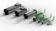
Linear Motors Used As Direct Drives

Increasing requirements regarding dynamic behaviour, accuracy and smoothness caused a technology shift also in the area of linear motion, namely the shift towards direct drive motors. As in rotary direct drive technology today there are linear direct drive motors where the mechanical load is directly connected to the moving part of the motor - without any further coupling. This stiff connection offers the same advantages as in rotary direct drive technology and allows for completely new machine designs.

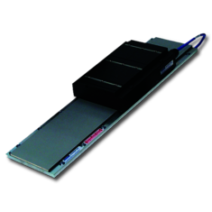
Compared to linear motion systems driven by rotary motors (see Actuators), direct drive linear motor systems do not have a principle limitation in length. The stationary magnet assembly can be stacked together from standard modular profiles to any demanded length. Because the moving part (winding) can be used for any desired move length, there is no change of performance depending on the length.

Leadscrew system in contrast do have critical limitations regarding speed and the inertia grows with the length of the leadsrew and therefore the stroke. Limitations in speed, high inertia and low stiffness still are the main disadvantages of other technologies compared to direct drive linear motor systems in longer stroke applications.

Do you have technical questions or need a quote?

Contact us today to talk to an experienced RECKONIC engineer!

Open Contact-Form

How Linear Motors Work

Linear motors in principle work as rotary motors do. Just imagine you cut a rotary motor and bend it until it is flat. A linear motor consists only of two components: the winding (forcer) and a steel plate with the magnets mounted (magnet assembly). The copper windings are embedded either into an epoxy or iron core and carry all the motor current.

The magnet assembly consists of rare-earth magnets mounted in alternating polarity on a rigid steel base plate. They produce a magnetic field perpendicular to the base plate. Current flowing in the copper windings produces the Lorentz force F = I x B which can be used for acceleration of the load inertia.

The Forcer normally is connected to the moving part of the machine whereas the magnet assembly is fixed to the stationary part of the machine. The airgap between forcer and magnet assembly is typically 0.6mm, but can vary by +/-0.3mm without causing a dramatical loss of performance.
 

Ironless and Ironcore Linear Motors

For ironless motors the coils get embedded into epoxy material. These motors are very well suited for very smooth linear motion. There is no attraction force between forcer and the u-shape type magnet assembly and the forcer. 

For iron core motors the coils are wounded around a laminated steel core. The steel is used to concentrate the magnetic flux, so that the force density is higher compared to ironless motors. Due to the iron there is a significant magnetic attraction force between the forcer and the magnet assembly which can be used as bearing preload. Like in conventional rotary motors iron core linear motors have also some cogging.

Sensors 

For the commutation, the digital speed control and the positioning operation of our linear motors we use displacement measuring systems or sensors. You can find more information under sensors. Encoders